0 Cart
Added to Cart
    You have items in your cart
    You have 1 item in your cart
    Total
    Check Out Continue Shopping

    DSX Tech

    Sensor Transfer Function Generator

    Sensor Transfer Function Generator

    Most people probably never paid attention in math class because they figured they'd never use it. Well, I did, so I'll share some of the tricks from doing so.


    This Excel sheet is very easy to use. Enter two voltages, enter the value at each voltage, and the equation generates to the side in two formats (multiplier and divisor). Nothing fancy about it, but now when you're trying to set up a new wideband, this will quickly give you what you need!

    Click here for the DSX Transfer Function Generator

    Some generic options:

    AFX2 Wide:
    •0V - 0.411λ
    •5V - 1.373λ

    AFX2 Standard:
    •0V - 0.618λ
    •5V - 1.098λ

    0-100psi Pressure Sensor:
    •0.5V - 0psi
    •4.5V - 100psi

    DSX Development

    DSX Development

    "Over engineered" and "over priced" are things people have been known to say about DSX Tuning products. I figured this is a good opportunity to offer some insight into what you're actually getting when you get a DSX product. There are usually a lot of small details you'd never even notice like tactile feel of installation or material compatibility, but it is all there.

    My very first fuel pump controller for a MAP sensor system was based on very simple logic. It was intended to be a simple replacement for a Hobbs switch, and it worked. When moving into a more production based option, logic switched over to a microcontroller for the ability to add a prime function on powerup and a little more defined operation (timing, hysteresis). This hardware proved out to work for the most part (minus the fact that Camaros randomly power up the ECM resulting in the automatic priming function being deleted). E38s and E67s functioned just fine with this controller.

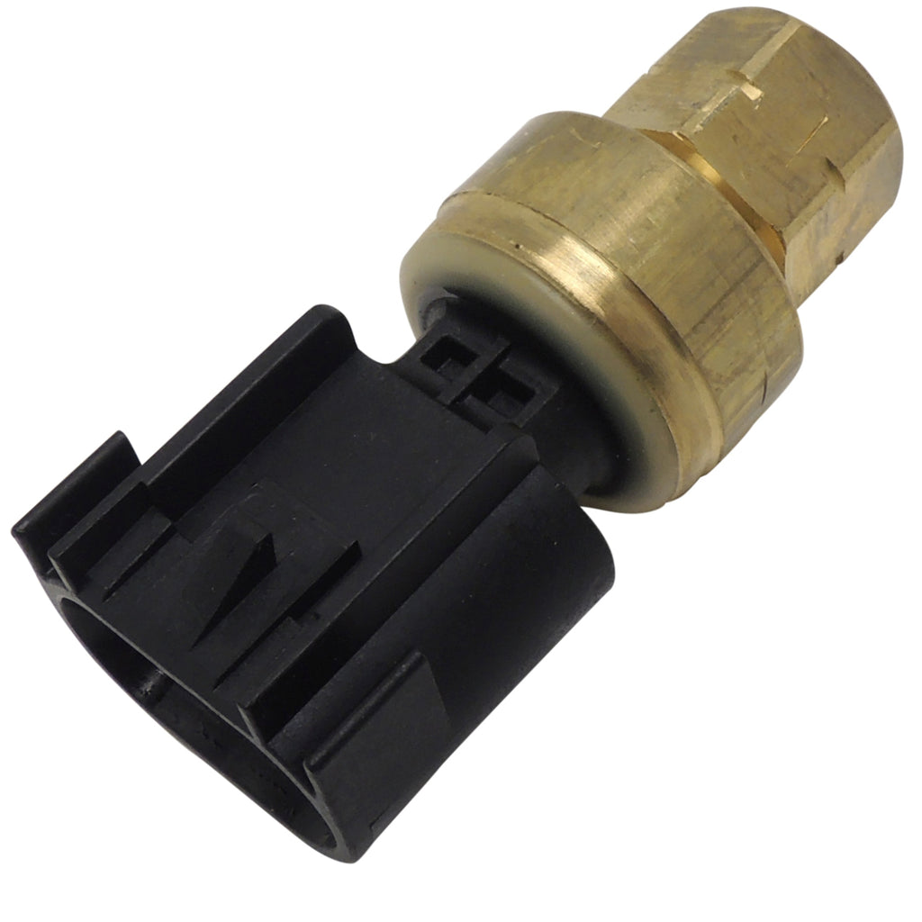
    Then, a new player entered the arena: the E92. Thinking nothing of it, I sent a couple controllers out for E92 applications, and every single one reported a failure within the first 10 minutes. Digging in a little deeper, it was discovered that a full power cycle of the ECM would kill them instantly. I was stuck.

    When something doesn't work, you have to develop a stop gap. The first thing I did was order an E92, flash it to a Corvette OS, and start poking it with a multimeter to see if there was a quick fix to make existing hardware work with a simple hack. The unfortunate reality was the 5V reference line on the E92 actually powers up to 6V for one second, then drops to 5V for the life of the complete ignition cycle. There was also an unknown of whether a huge voltage was feeding back into the ADC as well, but it became apparent the E92 wasn't going to be a quick easy adjustment. An idea had been rolling around for a while to use CAN data, and this event pushed that idea from concept to prototype rapidly.

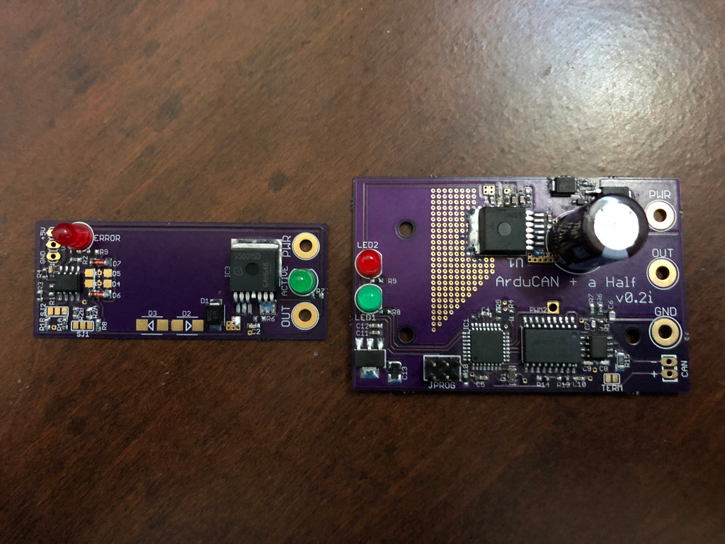
    So... The CAN pump controller was born in a very crude way. I had to somehow mate a microcontroller, a CAN interface, and a capable pump driver all into one package. The quickest way to do this was three different components working in unison. I made my own CAN interfaces which served as the gateway board between the microcontroller and the pump driver. Test subjects went out... They worked. They worked really, really well. People appreciated the soft start of the pump and the fact that now, the turn on point was 100% user controlled. People also appreciated the fact that they can now purge the pump completely from inside the car... No need to unplug the MAP sensor and plug into a baro sensor. Now, you could just key on, don't start the engine, and push the gas pedal to run the pump proportional to the pedal position. But there were two problems...

    Cost and time. Individual components and mating them together meant each component was expensive. It was also really time consuming and resulted in an assembly time of roughly two hours just for one controller. The right thing to do was just absorb this hard parts and labor cost without passing it on to the customer.

    The long term solution was to redesign the MAP sensor method in a way that would withstand torture. To do this, I worked with a friend I've made through the industry. I explained all of the requirements that had to be met and gave a general idea of how I wanted it to function, but I wanted to simplify it all.

    It got done. No more coding, no more microcontroller, 100% solid state operation complete with hysteresis and status LEDs, and to top it off... no more external fusing because now, a high side driver with error detection was in use and consequently could protect itself from turning into a small ignition system while giving a glaring red light to say something is wrong. To top it off, this thing can withstand massive voltage spikes. The controller loses the custom programming option, but ultimately, everything was only seeing one of two turn on voltages, which this board has based on a couple of solder jumper selections. While cost of parts went up slightly, the labor of assembly went down significantly because now, it was just a matter of soldering the wiring harness to the board and potting it out inside a 3D printed enclosure. The overall packaging was definitely an improvement.

    However... the CAN controller worked too well to just eliminate it. So now that is consolidated onto one board. Hard parts cost is similar to before, but the labor time will be significantly reduced as it won't have to be completely hand assembled anymore. With status lights, built in thermal protection, and a big factor of safety on the driver, it will be a robust and extremely capable controller for even pumps larger than what I use.

    The MAP sensor versions will be entering large scale production soon. Right now, they are all hand assembled. The CAN boards are still going through debugging, but they will make their debut later this year as an upcharged option for any system. The MAP controllers will remain as the standard for every system except the upcoming C7 system (which will ONLY be offered with the CAN controller).

    I hope this makes it clear that there's actually significant thought into every aspect of what goes out the door, and I hope it makes you feel a little better when you support DSX Tuning products.

    DSX Fittings

    DSX Fittings

    The small details that 99% of people never notice are the things I actually get some sense of satisfaction out of.

    I outsource the CNC machining of my custom fittings, but I handle the design and assembly 100% myself. I've opted to use fluorosilicone o-rings inside instead of Viton due to the far better chemical resistance (fluorosilicone is rated excellent for everything that might even touch the o-ring). I took the time to research proper gland design instead of just picking some dimensions that sort of work (which I found is what most places do unfortunately) so that the double o-rings seal properly without excessive installation force.

    Installing the o-rings is a pain in the ass, but I used my 3D printer to make an installation tool which significantly sped up the installation. I made a point to use an exceptional grease with PTFE to minimize the possibility of tearing the o-rings as well as give a better tactile feel upon installation. I wound up making a go/no go gauge which serves the purpose of fully seating the o-rings but also ensures that the fittings will fit a worst case scenario connection. It is true 0.375" diameter as opposed to most rails and sensors that come in around 0.373"-0.374".

    There's also a very small lip inside meant to align and seat the stainless steel retainer clip that goes in to keep it positioned properly at all times and make sure it doesn't wind up crooked with a possibility to come loose.

    These little things are what I enjoy scrutinizing. I just hope it shows through in the end!

    Fuel Pressure Explained

    Often times the term fuel pressure is used with little understanding of what it really means. This leads to confusion with respect to injector flow rate, and people lose sight of how their injectors really work. Understanding how fuel pressure works and is applied in both returnless and return style fuel systems is important if a user wants to properly set up their injector characterization and get predictable fueling. Knowing what to expect also allows a user to diagnose problems with their fuel system and ultimately make the vehicle function as intended.

    There are two pressures that people need to consider: rail pressure and effective (or differential) pressure. For the purposes of the rest of this article, it will just be called effective pressure. Rail pressure is self-explanatory; it is the pressure inside the rail. When you stick a fuel pressure sensor on the end of a rail, it is reading the pressure inside of the rail. While this number is important, it is only half of the story.

    Effective pressure is the actual applied pressure for the injector, and is the pressure differential ACROSS the injector. Effective pressure is what injector flow rate is ultimately based off of. When an engine is idling, there is a vacuum in the intake manifold. This vacuum pulls fuel out of the injectors, and increases the effective pressure across the injector to a pressure higher than the rail pressure itself. When a supercharged or turbocharged vehicle is in boost, the pressure inside the manifold is trying to push fuel back into injector, resisting the flow and decreases the effective fuel pressure below that of the rail.

    This concept is important because it changes how the fuel system needs to be set up in the PCM. There are two generic types of fuel system setups: returnless and return style. A returnless system does just as the name implies and doesn’t return fuel to the tank. Return style systems will bleed excess fuel back to the tank through the regulator. Return style systems hold a big advantage in that with a vacuum/boost referenced fuel pressure regulator, the system can maintain a CONSTANT effective fuel pressure, which can extend the range of fuel injectors and help them function at lower fuel demands as well.

    With a return system, the base pressure is set with the engine off, but the pump running. For a GM, this pressure is usually set to 58psi (factory fuel pressure in the rail). The vacuum/boost referenced regulator will help to change the pressure in the rail based on the pressure in the manifold. When an engine is idling, it may be pulling 20 inHg of vacuum, which translates to roughly 10psi. The reference to the regulator will allow it to adjust and lower the pressure in the rail to 48psi, resulting in 58psi effective pressure, which is the same as the base pressure. When the engine is making 10psi boost, the regulator will adjust and increase rail pressure to 68psi, again resulting in 58psi of effective pressure. The regulator will constantly bleed off pressure inside of the rail to maintain the same effective pressure at all operating conditions. This helps to prevent a loss of effective pressure during wide open throttle, and also helps to prevent injectors from having to run extremely low pulse widths to fuel at idle. A downfall of return systems is the fact that they circulate fuel through a very hot engine bay, ultimately carrying that heat back into your fuel tank.

    A return style system that isn’t variable will maintain a certain pressure inside the rail, regardless of what is happening in the manifold. For instance, take a GM system with the standard 58psi in the rail (usually there is a mechanical regulator near the pump to bleed pressure back into the tank and keep the rail itself at 58psi). No matter what operating condition (short of demanding more fuel than the pump can supply), pressure in the rail will always be 58psi (or pretty close). When idling at 20 inHg, this means effective pressure will rise to 68psi because the vacuum in the manifold is adding 10psi to the rails 58psi. This requires injectors to pulse shorter so as to not overfuel the engine and cause a rich condition. By contrast, when a naturally aspirated engine is wide open throttle, the manifold pressure is not in vacuum or in boost, so the effective pressure is the 58psi of rail pressure and nothing more. However, a boosted engine at 10psi will be resisting the fuel, causing effective pressure to drop to 48psi from the 58psi in the rail. This lowers the ultimate output of the injectors.

    Some returnless systems will actually vary the pump output to emulate a referenced system, or to offer more fuel pressure at higher demands and less fuel pressure at lower demands. Ford fuel systems modulate the pump in an effort to maintain effective fuel pressure at 3 bar. The Corvette ZR1 runs fuel pressure in the 30s until an increased demand is on the system, at which point it will ramp the fuel pressure up to 88psi in the rail. Systems like these use sensors that record the fuel pressure, and when combining that pressure with the manifold pressure, the PCM knows what the effective pressure is and will determine a pulse width for the injector accordingly. Systems like these offer the best of both worlds.

    Ultimately, what we need to know is the effective fuel pressure in any given situation though. GM uses manifold pressure to subtract away from the rail pressure (which it always assumes is 58psi) to calculate pulsewidth. By referencing the flow rate table, in which the flow rate at various effective pressures is programmed in, the PCM knows what flow the injector is capable of at any given operating system. To convert a GM vehicle to work with a boost referenced return system, one must simply populate all of the various pressures with the same flow value, since the effective pressure (and consequently injector flow rate) will remain constant, regardless of manifold pressure. Word to the wise, when you see injectors advertised to flow X amount of fuel at a certain pressure, if you have a boosted vehicle, they will actually flow less while in boost unless you have a boost referenced system!